Dewars and Coolers
Dewars, Connectors, and Flanges
Repumpable metal dewars are recommended for laboratory or R&D use. Advantages include rugged construction, low cost, long hold time, optional mounting flanges, a wide range of window materials, and shorter delivery time. The specified hold time is guaranteed for one year; re-evacuation may be required every year or two thereafter. Long life, permanently sealed glass dewars offer the advantages of small size and superior performance under mechanical vibration. Glass dewars generally require longer delivery times. Dewars with custom configurations or longer hold times can be provided.
Cold Stops: The cold stop is a field of view (FOV) limiting aperture, cryogenically cooled to block unwanted background radiation from reaching the detector. Judson defines the field of view as the angle f, which is two times the half angle defined by the cold stop and the edge of the detector (Fig. 1). Radiation at larger angles is blocked by the cold stop. Thus, the entire active area of the detector can see radiation entering from a cone angle of f. Theoretical D* improvement for BLIP detectors is more accurately determined by the angle q from the center of the detector. Note: Fig. 1 shows theoretical D* improvement for background limited (BLIP) detectors only. Actual improvement may be less than theoretical, particularly for large area detectors (1mm diameter or larger). When ordering a field of view, always specify the largest cone angle that will be needed for your optical system. Common field of view specifications include 30°, 45° and 60°. If the field of view is not specified by the customer, a standard 60° field of view aperture will be used.
Cold Filters: Judson's cold filters are mounted on the FOV and block background radiation from unwanted wavelengths. Cold filters can significantly improve D* for background limited (BLIP) detectors. Standard cold filters include the SP29 which has transmission from visible to 2.9µm. The SP35 has transmission from 1.7 to 3.5µm. Custom cold filters are also available for a wide range of wavelengths and bandwidths in the infrared. Typically, these cold filters come from stock overruns of major filter manufacturers. We can also mount cold filters supplied by the customer.
Metal Dewar Reliability: Judson's standard metal dewars are designed for long hold time and long life. Each metal dewar undergoes extensive leak testing before and after assembly. The dewars also go through extensive prebaking and postbaking after detector mounting to eliminate residual water vapor and outgassing. For FTIR applications, each unit is 100% tested for less than 1% ice band absorption after eight hours of operation. Each standard dewar comes with an SMA to BNC coax output cable.
Dewar Model | Type | Window Position | LN2 Hold Time (hours) | Outer Dimensions (inches) | Notes | Available Windows |
Sideview | Downview |
M204 | Metal | X | | > 8 | 2.5 Ø x 5.25 H | Fig. 34-1 | Sapphire (WG) ZnSe (WJ) KRS-5 (WK) Silicon AR Coated (WB) and Ge AR Coated (WE) |
M205 | Metal | | X | > 8 | 2.5 Ø x 5.31 H | Fig. 34-2 |
M200 | Metal | X | | > 12 | 2.5 Ø x 6.75 H | |
M201 | Metal | | X | > 12 | 2.5 Ø x 6.81 H | |
M108 | Metal | X | | > 8 | 2.5 Ø x 5.25 H | Fig. 35-1 SMA
Connectors on Dewar |
M209 | Metal | X | | > 24 | 3.5 Ø x 8.00 H | Fig. 35-2 |
| Window Code | Material | Transmission | Wavelength Range | Wedge Angle | Detector Series |
| WA | AMTIR | > 74% | 0.8µm - 6.0µm | 20' | J10D |
| WB | Si (Coated) | > 92% | 1.3µm - 6.0µm | None | J10D |
| WD | Ge (Coated) | > 90% | 7.8µm - 12.8µm | None | J15D12 |
| WE | Ge (Coated) | > 95% | 2.0µm - 14.0µm | None | J15D12, J15D14 |
| WG | Sapphire | > 85% | 0.4µm - 6.0µm | 20' | J10D |
| WI | ZnSe | > 74% | 0.5µm - 20µm | 20' | J15D12, J15D14, J15D16 |
| WJ | ZnSe | > 74% | 0.5µm - 20µm | 20' | J15D12, J15D14, J15D16 |
| WK | KRS-5 | > 72% | 0.5µm - 40µm | 20' | J15D22 |
Windows: Standard windows for Judson detectors are listed below, along with the Judson model number codes. Transmission curves are shown in Figure 3. All windows are .040" thick. Windows for FTIR or other coherent light applications have a nominal 20' wedge angle (0.33°) or a 1° wedge angle to prevent fringing interference.
Figure 3
| Window Code | Material | Transmission | Wavelength Range | Wedge Angle | Detector Series |
| | | | | |
| WB | Si (Coated) | > 92% | 1.3µm - 6.0µm | None | J10D |
| WD | Ge (Coated) | > 90% | 7.8µm - 12.8µm | None | J15D12 |
| WE | Ge (Coated) | > 95% | 2.0µm - 14.0µm | None | J15D12, J15D14 |
| WG | Sapphire | > 85% | 0.4µm - 6.0µm | 20' | J10D, J16D |
| WI | ZnSe | > 74% | 0.5µm - 20µm | 20' | J15D12, J15D14, J15D16 |
| WJ | ZnSe | > 74% | 0.5µm - 20µm | 20' | J15D12, J15D14, J15D16 |
| WK | KRS-5 | > 72% | 0.5µm - 40µm | 20' | J15D22 |
Metal Dewar Features
-
Rugged Construction
-
> 8 Hour Hold Time
-
One Year Warranty
-
Repumpable
-
Accurate Centering of Detector
-
Sideview and Downview
M204 or M205 Standard Metal Dewars: The M204 sideview and M205 downview are the recommended standard metal dewars for all Judson cryogenically cooled detectors, including J10D InSb, and J15D HgCdTe. An SMA to BNC coax output cable is included with each unit.
Figure 4
Figure 5
M200 or M201 Standard Metal Dewars: The M200 sideview and M201 downview dewars are similar to the M204 and M205 respectively, with the exception of dewar height and LN2 hold time. The M200 and M201 are 6.75" tall (Dimension "A") for >12 hours LN2 hold time.
|
Dewar Model |
Dimension | | | |
| |
"A" |
"B" |
"C" |
"D" |
|
M204 Sideview |
5.25 |
4.00 |
2.60 |
1.70 |
|
M205 Downview |
5.31 |
4.30 |
2.90 |
0.44 |
|
M200 Sideview |
6.75 |
4.25 |
2.87 |
1.70 |
|
M201 Downview |
6.81 |
3.63 |
2.25 |
0.44 |
Detector centered to within ±0.020 to O.D. of window retaining nut (at 77°K operating temperature).
M108 Metal Dewar with SMA Connectors: The M108 sideview metal dewar has two SMA connectors mounted directly to the dewar body instead of the backplate options. This configuration helps minimize the amount of space required for mounting the dewar in an optical system. The shield of the detector SMA connector is normally
grounded to the dewar body (see "Dewar Grounding and EMI"). They may be isolated from the dewar on request. The dewar ground pin allows independent grounding of the dewar body if needed.
M209 Metal Dewar for 24-Hour LN2 Hold Time: The M209 sideview metal dewar provides convenient, 24-hour hold time in a 3.5" diameter x 8" tall package (Fig. 7).
Dewar Cables: An SMA-to-BNC coaxial cable (Fig. 8) for connecting the detector SMA to a preamp is provided with each Judson metal dewar.
Detector Mount/ Flat Packs for Customer LN2 Cooling: Alternate packages are available for customers wishing to mount Judson detectors in their own dewars. Special care in handling is required; the customer should be familiar with clean detector mounting and dewar evacuation techniques. The DM1 Detector Mount (Fig. 9) is used to mount detectors into standard Judson metal dewars. The assembly includes a metal base and a FOV which can be bolted to the dewar cold finger. Flat pack carriers are also available for J10D and J15D Series detectors
(Fig. 10).
Metal Dewar Connector Options: Most Judson metal dewars are equipped with SMA connectors for detector output (Figure 11). The standard version is recommended. Where available mounting space is limited, the "B" version reduces overall dewar diameter at a nominal extra cost.
Figure 11
Dewar Grounding and EMI: The shield of the detector SMA connector is normally grounded to the dewar body. In this configuration the shield of the coax cable is common to the dewar, making the entire dewar body a shield and limiting potential EMI interference with the detector. The SMA's may be isolated from the dewar if the standard grounding scheme is suspected of causing ground loops or pick-up noise in the user's system. The cold finger ground lug is for optional use, to ground the detector separately from the dewar. Some detectors include a temperature sensor, which may also be used to ground the detector. Normally this ground is not required; the ground lug may be left unconnected.
DFM Series Mounting Flanges for Metal Dewars: DFM Series mounting flanges assist in mounting and positioning of Judson metal dewars to the customer's bench top or optical system. The DFM-1 is a dewar base mount, which is fixed to the bottom O.D. of the dewar using set screws (Fig. 12). The flange may be bolted to a horizontal surface such as a table or positioning stage.
Figure 12
RC2 Detector/Rotary Cooler Integral Assembly
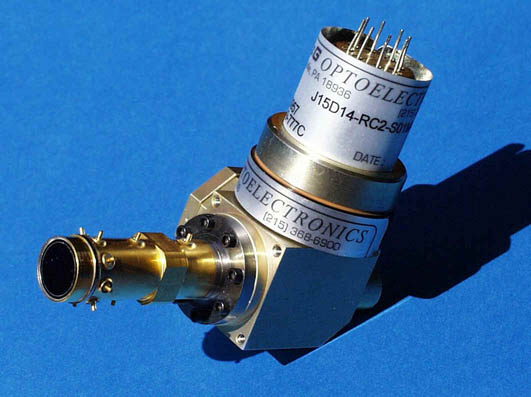
The RC2 microcooler is an integral Stirling engine with the detector directly mounted to the cold finger. Its 3.5 watt power requirement makes it ideal for use with a battery. Judson recommends rotary coolers when low power dissipation and portability are important. The RC2 microcooler fits easily in the palm of the hand and cools down to 77° Kelvin ± 0.5°K. The RC2 detector cooler assembly can be used with the J10D and J15D Series detectors. To determine performance of a detector with the cooler, typical specifications from the relevant detector series should be used. This cooler assembly is available with a plug in temperature control module which provides an adjustable temperature set point and requires 12VDC input.
Applications
-
Portable Infrared Radiometers
-
Environmental Monitoring
-
Thermal Imaging
-
Range Finding
-
Spectroscopy
-
Infrared Instrumentation
Design Features
-
MTTF
-
³ 2000 hours Dissipates 150mW heat load
-
Operates at 12V DC at 0.25A
-
Power requirement 3.5 watts
-
Hand held
Figure 15
Controlled Temperature Operation: This cooler has been specifically designed to maintain an infrared sensor at 77K. In normal operation, a 2N2222 silicon diode chip is attached adjacent to the infrared sensor and serves as the cold finger temperature sensor. At 77K, with a forward bias current of 1mA, the voltage across the base (+) to emitter (-) junction of the diode is typically 1.060 volts. (At 295K, it is 0.7 volts.) During the initial cooling, the cooler motor operates at peak RPM. Once the set point is reached, the motor throttles back to maintain temperature established by the set point. If the temperature sensor is left in an open circuit condition, it will appear as a max. voltage to the controller circuit and cause the cooler to throttle back immediately. Conversely, if the sensor leads are shorted together, the motor will operate at full RPM and the cold finger will stabilize at a temperature at which cooler power equals the sum of radiative and conductive thermal loads. The set point is placed at 1.060 volts at the factory. This can be adjusted for some other voltage via a temperature adjust pot on the control circuit board. The adjustment range is 1.0 to 1.1 volts.
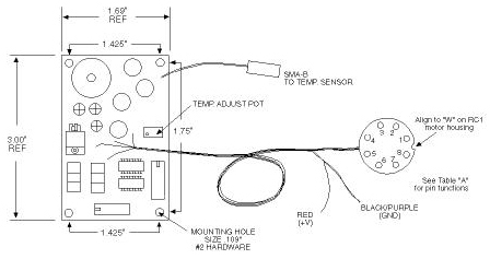
Figure 16
TABLE "A"
1 Motor Drive 0A 2 +5 Volt Hall Sensor 3 Hall Sensor 0A 4 Hall Sensor 0B
5 Hall Sensor 0C 6 +5 Volt Return 7 Motor Drive 0C 8 Motor Drive 0B
Click here to view table
 Click for more RC2 information.
Indium Antimonide Detectors with RC1 and RC2 Coolers |
Detector Model Number | Detector Part Number | Active Size (mm.) (dia.) | Operating Temperature (K) | Cutoff Wavelength (µm) | Peak Response (A/W) | Shunt Impedance (KW) | Typical D* |
J10D-RC2-R01M | 400361 | 2.0 | 80 | 5.5 | 3 | 2000 | 1.5E+11 |
J10D-RC1-R04M | 400308 | 4.0 | 80 | 5.5 | 3 | 500 | 1.5E+11 |
J10D-RC1-R02M | 400211 | 2.0 | 80 | 5.5 | 3 | 80 | 1.5E+11 |
Mercury Cadmium Telluride Detectors with RC1 and RC2 Coolers |
Detector Model Number | Detector Part Number | Active Size (mm.) (sq.) | Operating Temperature (K) | Cutoff Wavelength (µm) | Peak Response (V/W) | Typical Bias Voltage (V) | Typical D* (10KHz) |
J15D12-RC2-S050U-60 | 451139 | 0.05 | 80 | 12.0 | 30,000 | 0.1 | 5.0E+10 |
J15D12-RC1-S100U-38 | 450679 | 0.1 | 80 | 12.0 | 15,000 | 0.1 | 6.0E+10 |
J15D12-RC1-S01M-60 | 450921 | 1.0 | 80 | 12.0 | 1000 | 1.5 | 2.5E+10 |
J15D14-RC2-S01M-60 | 450956 | 1.0 | 80 | 13.3 | 1000 | 1.5 | 2.5E+10 |
J15D16-RC1-S01M-30 | 450993 | 1.0 | 80 | 16.6 | 750 | 1.5 | 2.0E+10 |
J15D20-RC1-S01M-60 | 450606 | 1.0 | 80 | 20.0 | 150 | 2.0 | 1.0E+10 |